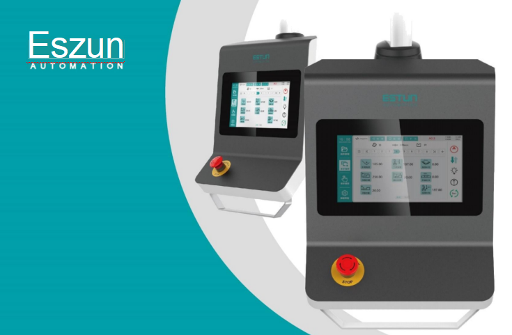
E310P Bending Machine Numerical Control Device
Operation manual
|
|
Prior to utilizing this product, it is imperative to thoroughly read this Manual and adhere to all safety precautions and instructions outlined herein. Mounting, operation, and maintenance procedures related to this product and the robot should exclusively be undertaken by reliable individuals who have received proper training and authorization from ESTUN. |
|
|
It is essential to ensure that this Manual is handed over to individuals directly involved in the operational process. |
|
|
For queries about unclear aspects of this document and post-sales service regarding this product, please use the contact details provided on the back cover to reach out to us. We are wholeheartedly committed to assisting you. |
Revision History

Preface
Overview
The purpose of this manual is to guide users on how to use this product in conjunction with control machine tools for production.
The manual covers the mounting, wiring, control functions, settings, debugging, and maintenance of the product.
Conventions
Meanings of Symbols
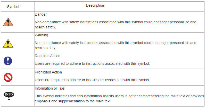
Following signs incorporated in this document shall have the following meanings.
Chapter 1 About E310P
Product Introduction
E310P is a dedicated CNC device for torsion axis bending machines. It embodies the accumulated technical expertise of ESTUN over many years and provides a comprehensive and economical solution for torsion axis bending machines, supported by unique drive control technology.
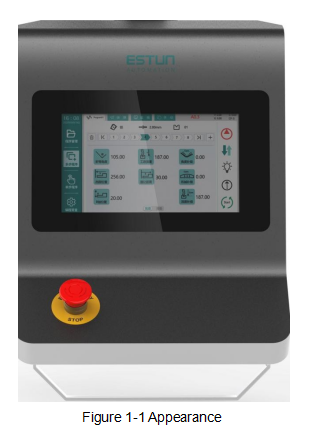
The operation of the E310P product is mainly realized through a touchscreen interface. Additionally, to meet user requirements, an E-stop button is mounted in a customized pendant cabinet, as illustrated in Figure 1-1.
Function Overview
The E310P CNC device upholds ESTUN's classic operating methods, allowing for control operations on bending machines through a straightforward and intuitive parameter configuration interface. Its interface is user-friendly, easy to grasp, and seamlessly aligned with the following control functions:
1.Supports four axes (X, Y, R, C).
2.Automatically calculates the stopper position based on bending angle, material, sheet thickness, and mold parameters.
3.Precise servo control of the X and R axes for high-precision back-gauge control.
4.Optional hydraulic or mechanical control for the C axis.
5.Angle and position programming.
6.Simplifies machine tool debugging and supports one-click restore settings.
7.One-page programming for quick and convenient programming, enhancing programming efficiency.
8.Direct control of holding time and yielding wait time without the need for external time relays.
9.Avoids mold interference or collisions.
10.Backstroke distance adjustment function to improve machine tool efficiency.
11.Automatic clamping point position adjustment.
12.Provides monitoring pages for real-time viewing of input, output, slide, and alarm status information.
13.Automatic zero adjustment for the R axis.
14.Material and mold attribute editing.
15.Work-piece processing in various modes (JOG, single, continuous).
16.Use of metric and imperial units, as well as multiple languages.
17.IO ports can be freely numbered and have self-checking functionality.
18.Unidirectional and bidirectional location functions.
19.Yielding escape function.
20.Parameter tuning and teaching.
21.Manual axis movement.
22.Power-off position memory function, providing on-site protection for parameters,
position, and programs.
Appearance Description
For ease of description, a representative example is illustrated below, as shown in
Figure 1-2.
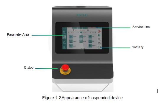
The detailed description of the product's components, as shown in below:
Service Line: The service column displays the machine tool status, work-piece count, alarm information, and Y,X,X,and C-axis position information.
Parameter Area: The parameter information changes based on the selected interface.
E-stop: The E-stop button is used for immediate stop in case of anomalies. Pressing this button cuts the power source to the machine tool system, and halts equipment operation to ensure personal and equipment safety. The E-stop button can be released and reset by rotating it when pressed.
Start/Stop Key: Oil pump start  Single-step/Continuous
  Lighting output
  Jog to open
  Stop running
Electrical Specifications
Chapter 2 Mounting and Wiring
In general, ESTUN engineers will assist users in the mounting of this product. However, if users prefer to perform the mounting themselves, it is essential to carefully read this chapter, which outlines mounting steps and important considerations to achieve the desired assembly.
2.1 Mounting Precautions
2.2 Wiring Instructions
2.2.1 Signal definitions
2.2.2 Terminal wiring
 The connector can only be inserted into the corresponding slots on the PCB in one direction. Before wiring the connector, it is advisable to mark its left and right ends for user reference in ensuring the correct port numbering during wiring.
The steps for wiring the connector are as follows:
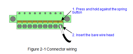
Step 1 Locate the correct terminal on the connector and use a suitable tool, such as a screwdriver, to press and hold down the corresponding spring button.
Step 2 Strip approximately 6.4 mm (1/4 inch) of the insulation from the end of the wire to be inserted into the terminal.
Step 3 Insert the bare wire into the terminal by 90%, then release the spring button. The inner metal teeth will securely grip the bare wire.
Step 4: Ensure that the inner metal teeth grip the exposed part of the wire, not the insulation, as shown in Figure 2-1.
Step 5 Wire all terminals and double-check the connections upon completion.
Step 6 Firmly insert the connector into the corresponding slots on the PCB. The connector can only be inserted in the correct direction.
2.2.3 Shielded cables
 Ensure that both ends of the cable are shielded, such as at the control device and servo motor.
Shield each cable by following the method shown in Figure 2-2 and using the following procedure:

Step 1 Strip the cable jacket until it reaches the edge of the wire fitting.
Step 2 Ensure that the length of the shielding wire can wrap around the nearest grounding bolt once.
Loosen the nut on the grounding bolt and wrap the wire clockwise around the nut, then tighten the nut.
Step 3 Connect the other wires within the cable to the terminal box.
2.2.4 Mains Voltage
2.3 Grounding Instructions
2.3.1 Ground classification
2.3.2 External grounding design
-Casing Grounding -Power Terminal Grounding -Cable Shield Grounding
2.4 Protection Measures
2.4.1 Electromagnetic Compatibility (EMC)
2.4.2 Mounting precautions for compatibility
2.4.3 Addition of FWDs to relays
Chapter 3 Function Settings
3.1 Sequence Diagram
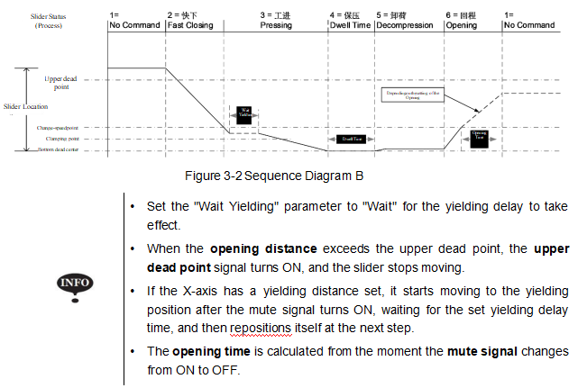
The complete bending process is shown in Figures 3-1 and 3-2 to illustrate the working conditions of various components. This helps users understand
the control timing of the E310P CNC device and facilitates a better understanding of the product.

3.2 Password Protection
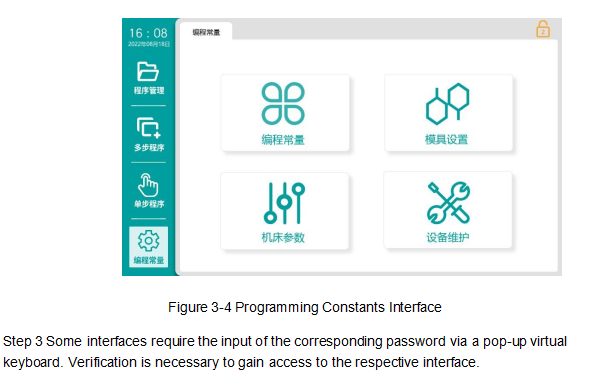
E310P uses passwords to protect access to different interface operation permissions. Typically, after the device is powered on, you can set basic operation parameters for single-step, multi-step, and tooling interfaces.
To perform teaching operations, system parameter settings, and diagnostic operations, different passwords are required. You must pass the verification process before you can proceed.
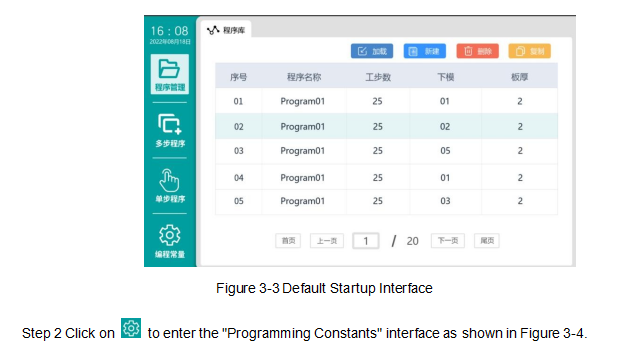
The specific steps for entering are as follows:Step 1 After the system is powered on, wait for the device to enter the default interface, as shown in Figure 3-3.
3.3 Port Configuration
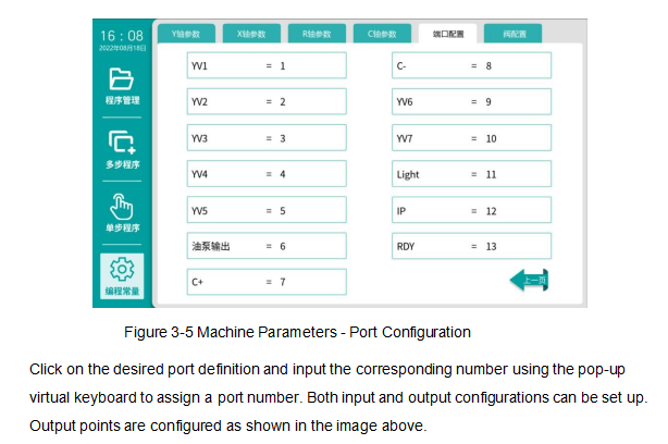
The numbers displayed on the interface are signal designations and correspond to input port designations, such as "1" on the interface corresponding
to input port port designation "l1" and output port designation "O1". These numbers do not refer to pin numbers.
3.4 Valve Configuration
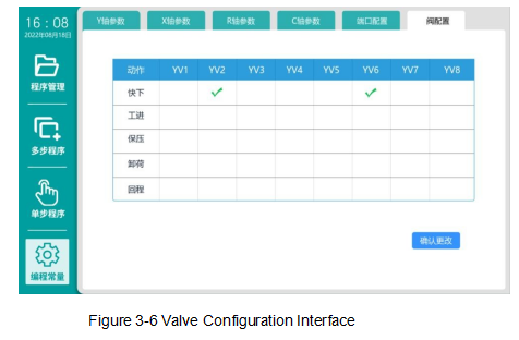
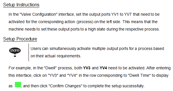
To assign numbers to various valves, you need to access the "Machine Parameters" interface with top-level permission, and then select "Valve Configuration", as shown in Figure 3-5. In the "Valve Configuration" interface, it will list the bending processes and allow users to customize which output ports (YV1 to YV7) should be activated when entering a specific process, as shown in Figure 3-6.
3.5 Axes
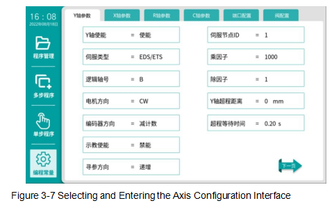
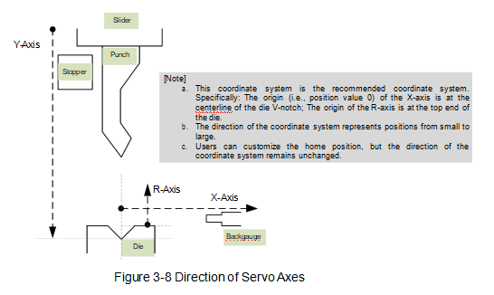
The professional term "Axis" used in CNC knowledge refers to the reference direction along which a machine tool component can move linearly or rotate. The E310P can control the movement of the back-gauge (X-axis) and the vertical movement (R-axis), the up-and-down motion of the slider (Y-axis), and the compensation for deflection of the lower worktable (C-axis).Among these, X, Y, and R can be driven by servo motors, referred to as servo axes, while C can be accomplished using hydraulic or mechanical methods, referred to as auxiliary axes.To enable and configure the parameters for these axes, you need to access the "Parameters" interface with top-level permission, and then select the axis parameter option you want to set, taking "Y-axis parameters" as an example, as shown in Figure 3-7.
3.5.1 Servo Axes
Before setting the parameters for servo axes, it's important to define the directions of these axes in the E310P, as shown in Figure 3-8.
3.5.2 Auxiliary Axis
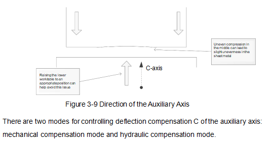
Deflection compensation would ensure the accuracy of the bending process. During the bending process, the main force is applied to the sides of the punch, which causes uneven compression in the middle of the sheet metal. This situation can be avoided by slightly raising the lower worktable through precise tuning and use of deflection compensation, as shown in Figure 3-9.
3.6 System Parameters
3.7 Programming Constants
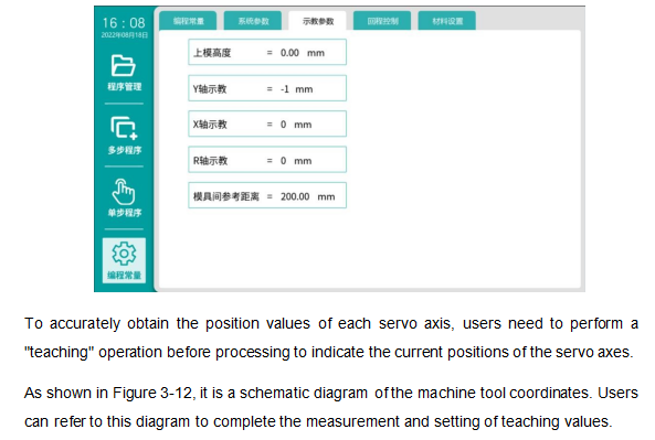
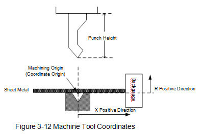
3.8 Teaching Parameters
3.9 Material Setup
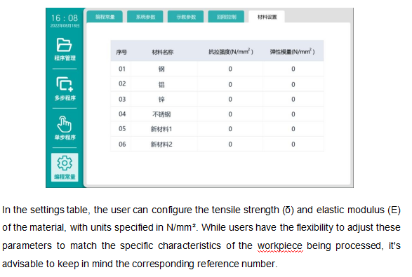
E310P will automatically calculate the bending depth based on the "Material" set in the programming, depending on the material sheet set by the user in the programming constants.Sheet metal possesses flexibility, and ignoring this characteristic can result in significant errors during the bending process, leading to poor bending precision. Recognizing this,E310P offers users six pre-defined material options with corresponding reference numbers. When performing single-step or multi-step programming, these selections will influence the actual bending depth through internal calculations.
3.10 Data Exchange
3.10.1 Parameter recovery
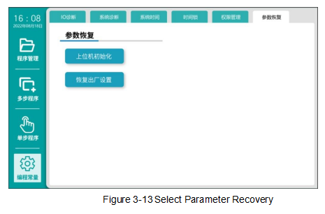
E310P allows for the recovery of machine parameters. After making adjustments to the parameters, users can save the current parameter settings to prevent unintended modifications later on.To enable and configure these axis parameters, you should first access the "Parameters" interface using top-level permission, and then select "Equipment Maintenance", as illustrated in Figure 3-13.
Chapter 4 Diagnosis and Monitoring
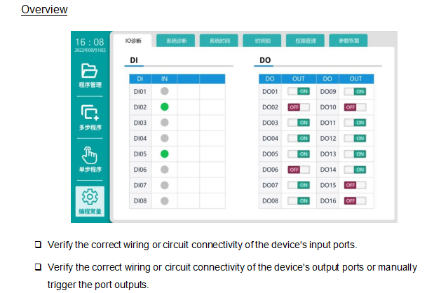
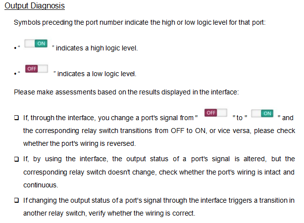
E310P provides a " Diagnosis" interface that facilitates hardware self-check operations for users. This chapter guides users on how to perform diagnosis on relevant hardware components through the interface. To enable and configure these parameters for the axes, you should first enter the "Parameters" interface using top-level permission, then click on " Maintenance", and proceed to " IO Diagnosis" or " System Diagnosis" for further operations.
4.1 IO Diagnosis
Input Diagnosis
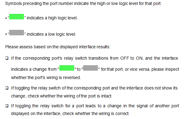
Toggle the corresponding relay switch for each port, and the device will detect changes in its signal.
4.2 System Diagnosis
4.3 Status Monitoring
Chapter 5 Debugging Guide
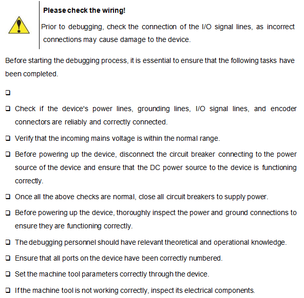
There are various methods for machine tool operation and debugging. This section will primarily guide users on how to debug the machine tool using the product, to ensure that the CNC device integrates well with the machine tool.
5.1 Preparation
5.2 Detection Signals
5.3 Valve Configuration
5.4 Servo Setup
The movement of each axis of the machine tool relies on the operation of the motors, which are controlled by servo drives. Before using servo motors to control the machine tool's operation, it's crucial to correctly set the parameters of the servo drives.The E310P control unit supports two types of servo drives: ED3L and ETS. Both of these are dual-axis servo drives, which means that one drive can control the movement of two axes simultaneously. For detailed instructions on configuring the drive parameters, please refer to the"Communication Settings" section in Appendix B.
5.5 Axis Parameters Setup
5.5.1 Servo parameters setup
5.5.2 Adjustment of operation direction
5.6 Search
5.7 Debugging slider movement
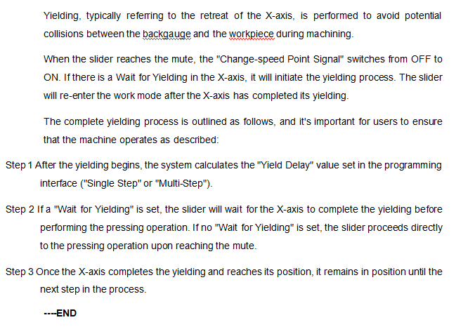
5.8 Check for Yielding
5.9 Opening Parameters Setup
5.10 Instructions for Setup Change
5.11 Angle Programming
The E310P control unit can automatically calculate the bending angle, but users must set the required parameters as listed in Table 5-2.

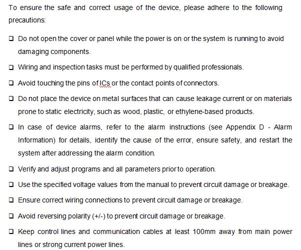
Chapter 6 Maintenance Guidelines Precautions
6.2 Routine Inspection
For routine inspections, please refer to the provided checklist.

6.3 Regular Inspection
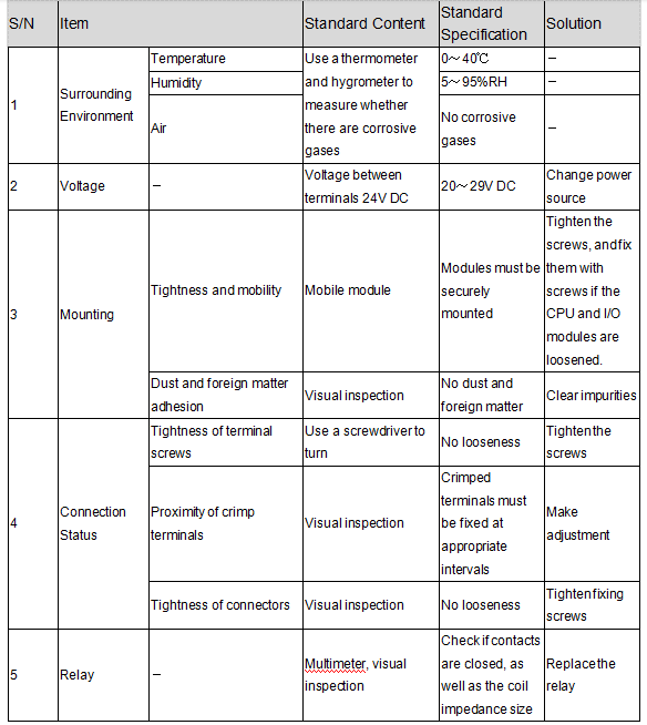
The following lists all items that must be inspected once or twice every 6 month to 1 year, and the same is required when the device is removed
or modified, or when wiring is changed, as shown in Table 6-2.
Table 6-2 Checklist for Regular Inspection
Appendix A: Terminology and Abbreviations
Appendix B Communication Settings
Appendix C List of Parameters
Appendix D Alarm Information
End